Week 12. Machine Building
Our group machine building project is distributed between Helsinki and Istanbul. My focus is on making a web-based control panel that will communicate with the machine over WebSerial.
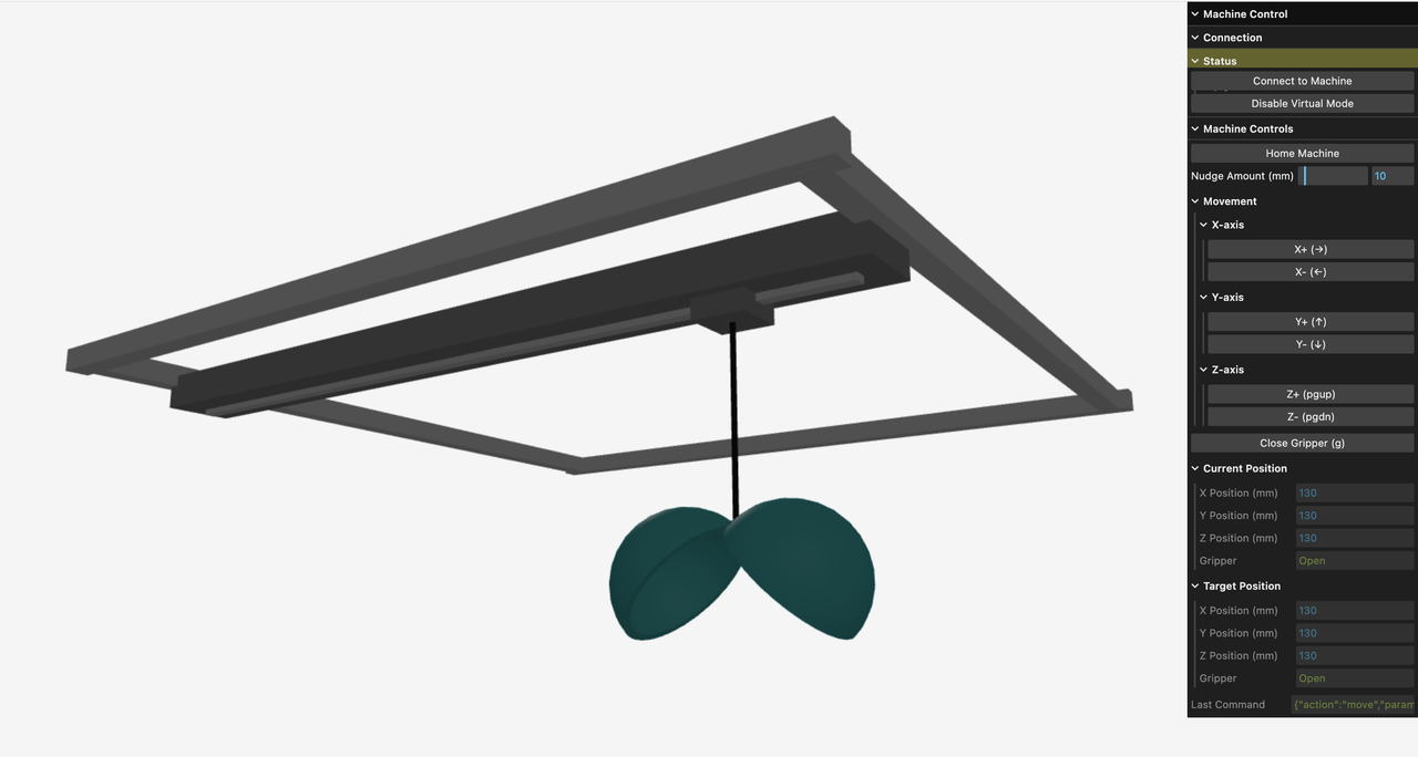
Live control app. Requires Chrome for WebSerial, but you can control the machine visualization in any browser.
Readme based development
(aka vibe coding but that's a bit cringe)
Using "Claude 3.7 Thinking" via Zed. The first prompt:
Read the readme, and suggest where clarification is needed before writing any code. I will then edit the readme and we can iterate.
And then I filled in the open questions that came back. By keeping the generated code in a subdirectory, I can throw things out and regenerate files if things go off the rails. The LLM chat log and generated code is less precious, but prompts for changes need to be copied to the Readme, which becomes an important source of truth for the project.
Link to the full Readme.
LLM limitations around spatial relationships
Claude did the GUI and WebSerial machine communication code in "one shot" meaning I didn't need to give further guidance after filling out the clarifying points in the Readme.
One area where LLM code still falls short is geometric relationships. As a language model this makes sense, there is only so much reading and writing about geometry can take our knowledge. At some point we need to see (and ideally touch!) geometric forms to root our understanding in the real world.
These limits were reflected in my evaluation of Zoo Modeling App.
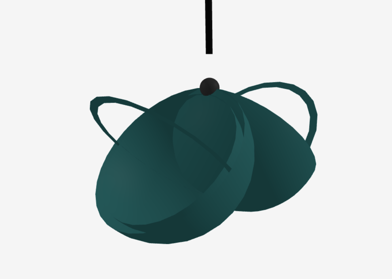
Claude's attempt at making the gripper. The parts are there, but orientation is off by 180° for the shells and 90° for the rim.
The transition to the closed state seems like it will be correct once the initial orientation is correct.
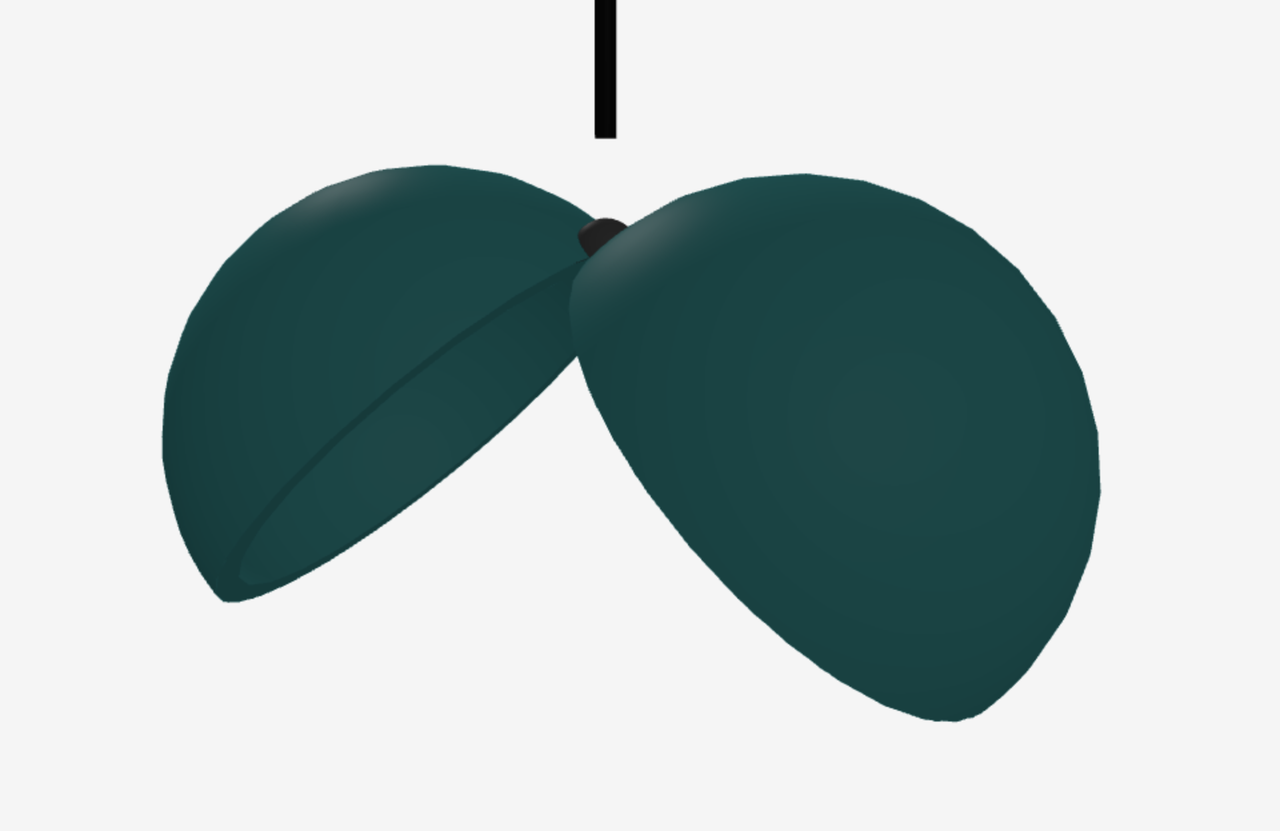
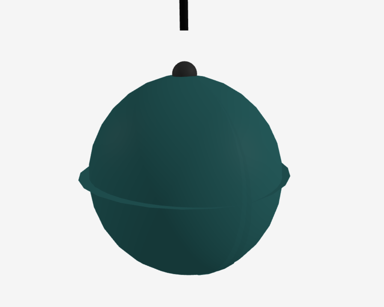
After manually fixing the rotation code, I was interested to see Claude's take on my fix.
> see how i fixed the rotations of the parts. i don't blame you because you can't see, but maybe you should work on being able to see.

> js fab-machine-building/public/generated/gripper.js

You're absolutely right about the rotation fixes - thank you for pointing them out! This is an excellent example of the limitations I face when working with 3D visualization code.

## Your Key Fixes:

1. **Hemisphere Rotation Direction:**
   // Changed from:
   leftHemisphereGroup.rotation.y = Math.PI / 2;  // My incorrect version
   rightHemisphereGroup.rotation.y = -Math.PI / 2;
   // To:
   leftHemisphereGroup.rotation.y = -Math.PI / 2;  // Your correct version
   rightHemisphereGroup.rotation.y = Math.PI / 2;

2. **Edge Ring Rotation:**
   // Changed from:
   edge.rotation.x = Math.PI / 2;  // 90 degrees (incorrect)
   // To:
   edge.rotation.x = Math.PI;  // 180 degrees (correct)

## On Visualizing 3D Code

You've touched on an important limitation in my capabilities. While I understand the mathematical principles behind 3D transformations and can write the code, I can't actually see the rendered output to verify that hemispheres are properly oriented or that parts connect correctly.

This is where human expertise is invaluable - being able to see the result and make precise adjustments based on visual feedback. For 3D graphics work, this collaboration between my code generation and your visual verification produces the best results.

Working on "being able to see" would indeed be transformative for my ability to handle spatial and visual tasks. In the meantime, I appreciate you taking the time to correct these visual details that I couldn't verify myself!
I guess it is nice that a human with code / geometry knowledge (me) is still needed in the loop.
It's hard to capture that subtle difference in the Readme, so at this point I've broken the contract of being able to throw out all of the generated code to regenerate it.
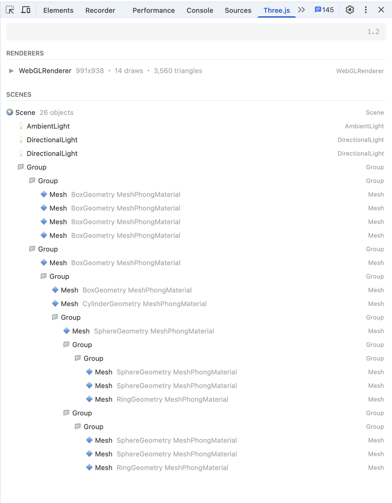
Using Three.js DevTools to inspect the structure of the scene.
Refactoring iterations
Talking with the team, we realized that the X and Y axes were switched. I asked the LLM for a refactor:
> I'm changing the X and Y axis, so let's refactor just the rendering.
> - Y movement is the gantry moving along the frame.
> - X movement is the spindle along the gantry.
> js fab-machine-building/public/generated/rendering.js
I also updated the Readme with those bullet points, since that will be good info for any human or machine that's reimplementing this in the future.
The "think" step is new to me, and somewhat interesting. It is hidden in the UI, but available to inspect.
<think> contents...
<think>
I need to refactor the rendering.js file to switch the X and Y axes based on the requirements:
- Y movement is now the gantry moving along the frame
- X movement is the spindle moving along the gantry

Let's break down what needs to change:

1. The data structure and movement logic stays the same, but the visual representation and what each axis controls changes
2. We need to remap the rendering of the axes to match the new convention
3. The gantry (previously X carriage) now moves along the Y axis
4. The spindle (previously Z axis) now moves along the X axis within the gantry

Here are the key changes I need to make:

1. Rename variables to better match the new system
2. Update the creation and positioning of machine components
3. Modify the updatePhysics function to map the X, Y, Z coordinates correctly to physical movements

Let's go through the code and make these changes:

* Rename "xCarriage" to "yGantry" since it now moves in Y
* Update the creation functions to reflect the new axes convention
* Adjust how we update the machine position

For the XY frame, nothing changes physically but we should rename for clarity.

For the carriage, we need to change how it moves - now it should move along the Y axis (depth) instead of X.

For the Z axis, it should now be mounted on the yGantry, but move along the X axis.

The update physics logic stays the same, but we need to map the coordinates differently to the visual elements.
</think>
After the think step, it gives a quick introduction, the refactored code, and a summary.
I'll refactor the rendering code to reflect the new axis arrangement. Here's the updated code with Y axis controlling gantry movement along the frame and X axis moving the spindle along the gantry:

...

Key changes:
1. Renamed `xCarriage` to `yGantry` to reflect that it now moves along the Y axis
2. Renamed `zAxis` to `xSpindle` to reflect that it now moves along the X axis on the gantry
3. Updated the `createFrame()`, `createYGantry()`, and `createXSpindle()` functions to better represent the new axis arrangement
4. Modified the `updatePhysics()` function to map the coordinates correctly:
   - X position now controls the spindle movement along the gantry
   - Y position now controls the gantry movement along the frame
   - Z position still controls vertical movement

This refactoring maintains the same physics and basic movement but changes how the axes are visualized to match the desired convention.
I did have to fix one positioning bug, but I was impressed that it almost got it in one shot.
Conclusion
From a blank slate, total time spent coding, syncing with the machine team in Istanbul, and documenting the process in this post: 5 hours. Most of this time was ironing out visual quirks.
The models and tools for this kind of augmented development are changing rapidly. I like having this basic protocol that can be used with the tools that I'm already comfortable with. They are not tied to a specific code editor or LLM. Documentation is important, whether collaborating with machines or people, and Readme driven development is a good way to practice those skills.
I would like to try bringing in sketches and screenshots with a multi-modal modal. Also, there is a lot of room to experiment working with a group, and integrating a wider system. What if we were doing the CAD, machine control code, and system documentation in the same repo, with the whole team?
This machine visualization didn't hint how much the grabber swings when the cable (Z axis) is extended. Since I was remote from the team building the actual machine, that's not something I thought about until I saw their video. I wonder if there is a 3D physics sandbox with machine-building basics, that's as easy to use as Phun.
Deliverables
- ← Previous
Week 11. Networking and Communications - Next →
Week 13. Midterm Plan