Cuttle.xyz evaluation
I'm on the small team building Cuttle CAD for makers. It is a browser-based 2D design app, with parametric and scripting features. Because of this, it is the parametric design workflow that I'm most comfortable with. This week I learned the basics of a handful of 3D CAD software, and I wanted to end the week with a physical object.
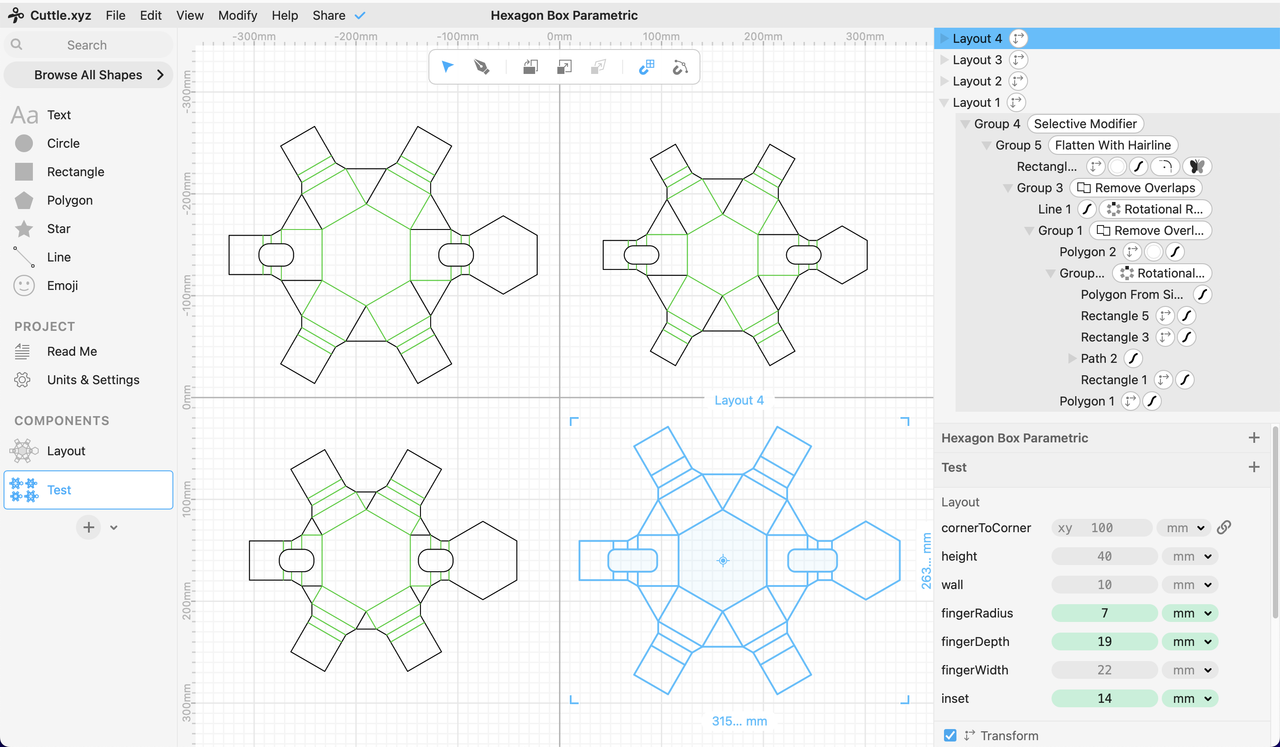
Cuttle interface, showing the same component as four instances with different parameters.
Using parameters in Cuttle is different than the constraint-based modelling in SolveSpace and FreeCAD. In Cuttle, parameters are emphasized in the interface, and there is not a concept of constraints. This means that to make shapes that a relative to each other, you have to do more math in the scale and position parameters of the shapes. Instead of "attach the left edge of the rectangle to the right edge of the polygon" in Cuttle it is more like "set the position of the rectangle relative to the size of the rectangle and polygon". Cuttle does feel like it is missing some basic constraint-based modelling features, but there is a tradeoff with the user experience and runtime complexity. Constraint solving is a can of worms, and Cuttle has decided to leave that can closed for now.
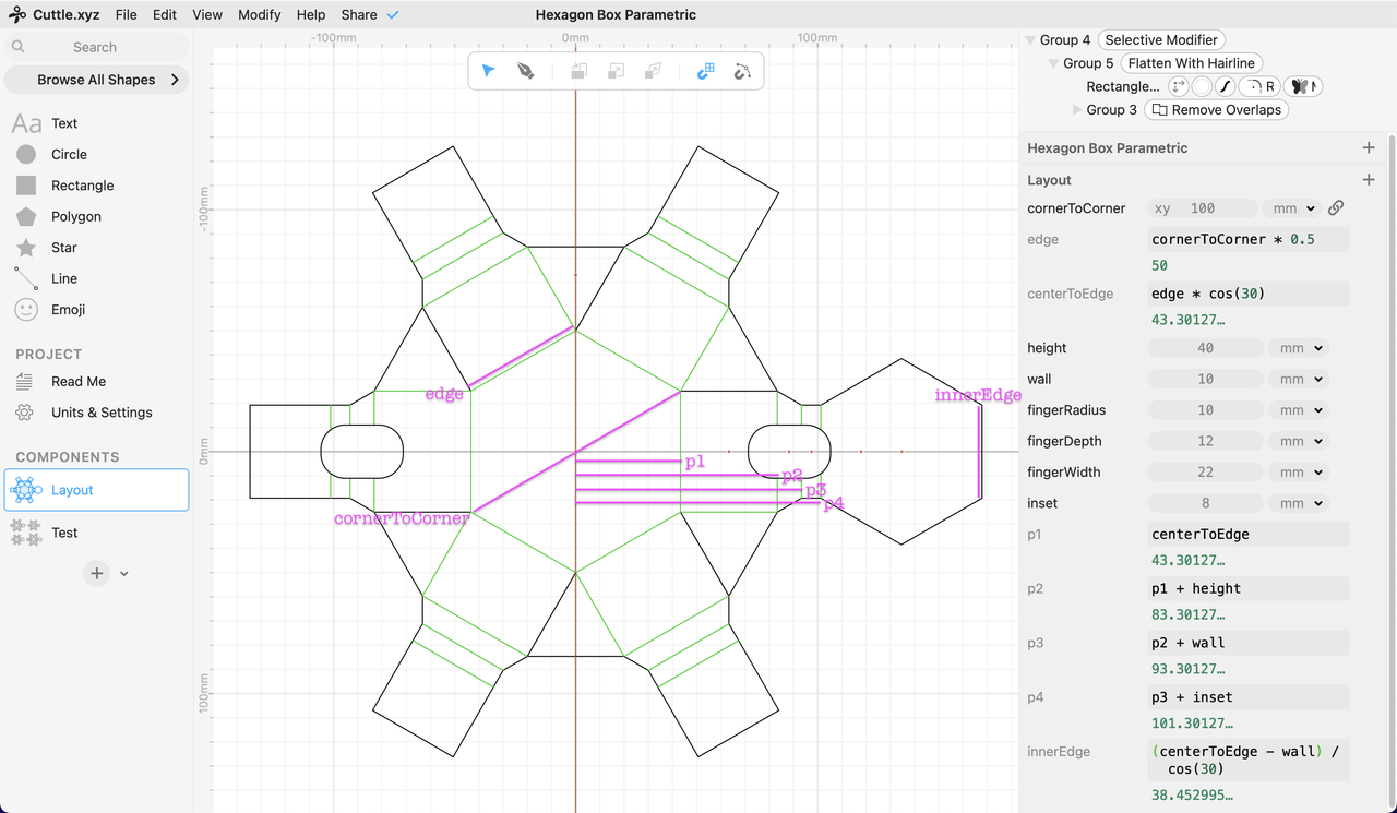
Cuttle pro tip: make any reused math expressions into parameters. This screenshot labels these derived parameters where they are used in the design.
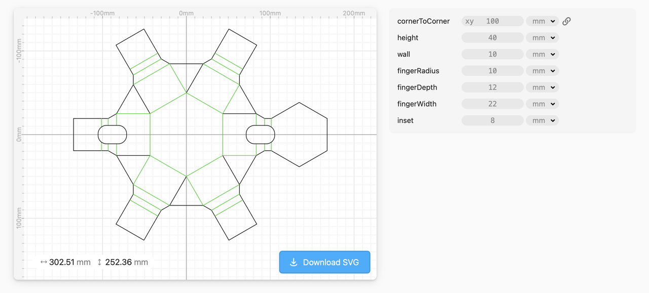
Cuttle projects have a "read me" section where you can add documentation of your project, and embed certain components. The parameters list in this view is simplified; the derived parameters are hidden.
Result
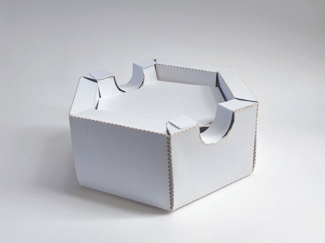
Scale model, made with lasercut cardstock.
Published design, where you can change parameters: Cuttle Parametric Hexagonal Box
See my quick rant encouraging physical prototyping with everyday materials.
Reference
- ← Previous
FreeCAD evaluation - Next →
CAD – Cardboard Aided Design